|
MSP430 Breadboard Interface
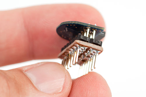
The tiny MSP-eZ430D target board is a very compact PCB,
and has a double row of breakout pads, making all 14 pins
easily accessible.
However, while the pin spacing is the standard 2.54mm (0.1"),
the spacing between the rows is also 2.54mm, which means it
cannot staddle the centreline of a breadboard
(spacing required to straddle it is 7.62mm, or 0.3").
I wanted to be able to easily plug an MSP430 into breadboard, as breadboard
is ideal for prototyping electronic circuits.
Version #1 - soldered version
Using two 7-pin lengths of double header pins, and a 7x4 section of vero board,
I built a small adapter that allows an MSP-eZ430D target board to be plugged into
a breadboard, straddling the centreline.
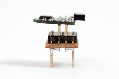
MSP-eZ430D atop completed breadboard adapter
One row of pins in each double header pin was pushed down (to pass through the vero board),
while the other row was pushed up (to go into the MSP-eZ430D).
The traces on the underside of the vero board were cut down the centre, as shown below.
tracks on vero board cut down the centre
The resulting adapter now plugs into breadboard, straddling the centreline.
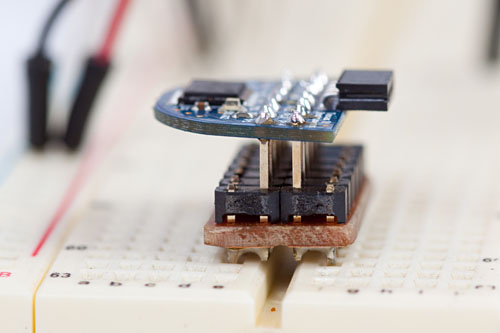
completed adapter plugged into a breadboard
The MSP-eZ430U debugging interface can still easily be connected to the MSP-eZ430D target board,
to allow in-situ debugging and programming.
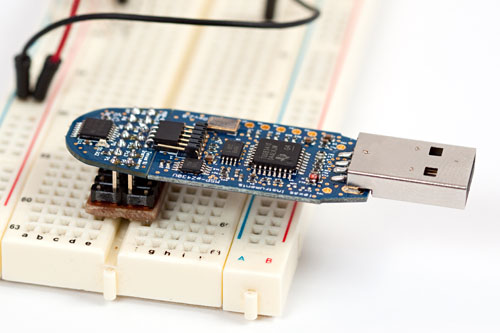
using the USB debugging interface
Version #2 - removable version
Rather than soldering the MSP-eZ430D directly to the adapter,
I also tried soldering a header socket on the top of the vero board,
allowing header pins on the MSP-eZ430D to be plugged into the
header socket.
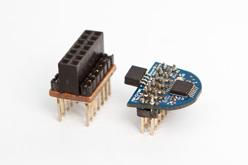
MSP can be removed from this breadboard adapter
This version allows the MSP-eZ430D to be removable from the breadboard adapter.
last updated 24 Mar 2026
| 
