|
Solder Fume Extractor
This page describes a solder fume extractor that I built, designed to draw away the fumes from my
soldering iron when working on electronics circuits.

completed solder fume extractor
Background Info
I hate the smell of soldering fumes, and have been meaning to build/buy a fan for some time.
After recently seeing a soldering fume extractor on kickstarter that was a lot more expensive than
I was expecting for a fan with speed control and a carbon filter, I decided to build one myself.
I already had most of the components in my shed, salvaged from various items
that I had pulled apart over the years. The only components that I had to purchase
for this build was the PWM fan speed controller and the carbon filter.
I enjoy projects like this, as I get a lot more enjoyment out of the building process
compared to just buying an off-the-shelf item that will do the same task.
Component List
Here is the list of components used to build the solder fume extractor.
- PWM fan speed controller
- 1N4148 diode
- 1K resistor
- BD437 NPN transistor
- 120mm 12v fan
- 12v 1A DC power supply
- small section of vero board
- activated carbon filter
- aluminium and mounting hardware
Circuit Description
I was originally intending to build a 555-timer-based PWM controller from scratch,
but found some cheap PWM controllers on eBay that looked suitable.
The PWM controller I purchased was listed as
"5~12V Square Wave Signal Generator Oscillator Fan Speed adjust for Arduino PWM"
(listing is here),
with the following specifications:
- Input Voltage range: DC 5~12V
- Output current: can reach 300mA+
- Frequency: 22Khz
- Size: 27*16mm
- Oscillation cycle: 40~50us (frequency approximately 20~25kHz). In other words, a square wave pulse is generated about every 45us.
- Duty Ratio adjustable range: approx. 5%~95%
- output voltage is about 2V lower than input voltage
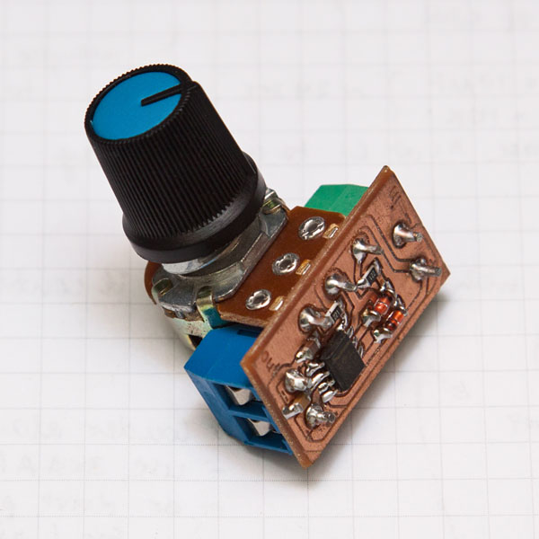
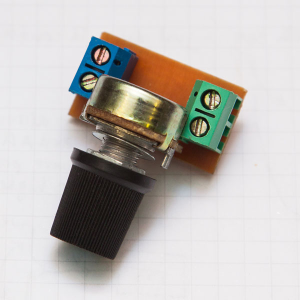
One of the reasons I chose this PWM controller is it's very small size:
PWM fan speed controller
(for size reference, that's 4mm grid paper behind it)
When I purchased the PWM controller, I assumed 300mA should be plenty for a 12v fan - but some tests with a multimeter
and a 12V power supply indicated the 120mm 12v fan I was intending to use was drawing about 600mA at 12v.
The solution was to use a transistor to drive the fan, triggering the transistor with the PWM controller,
as described below.
Schematic
The finalised circuit diagram is shown below. The transistor, diode and resistor
were mounted on a small piece of vero board, with some header pins providing a removable connection for the fan.
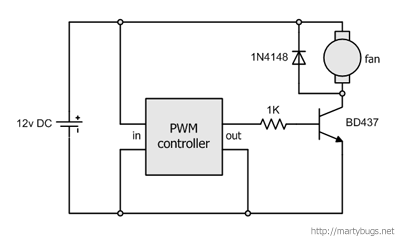
solder fume extractor - circuit diagram
(click for larger version)
Construction Details
A case was built using recycled aluminium, with some angled aluminium pieces holding the carbon filter in place.
The PWM fan speed controller was mounted under the top of the case, the vero board and transistor
attached to the side of the case, and a 5.5mm power socket was glued to the side.
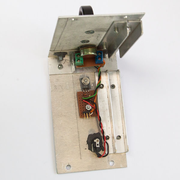
electronics mounted inside the case
The header pins on the vero board are for connecting the fan. Note that only two of the pins are used to provide
power to the fan - the middle header pin is un-used.
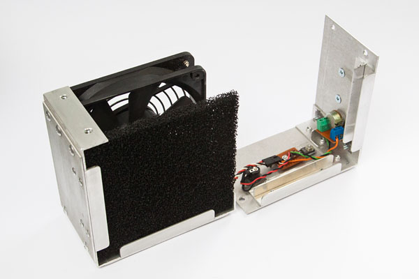
ready to close the case

rear of the completed solder fume extractor
The handle on top of the case is recycled from the front of an old Dell server,
and the 12v 1A DC power supply was recycled from some unknown electronic appliance.

front of the completed solder fume extractor
Operation
The completed solder fume extractor works well, and has plenty of suction for removing solder fumes.
The potentimeter allows the fan speed to be adjusted from almost zero revs to high speed,
allowing a compromise between the amount of suction required, and the amount of noise I'm prepared to put up with
(at full speed, a 120mm fan moves a lot of air, and hence tends to make a bit of noise).
last updated 24 Mar 2026
|
|