|
Fixing 3rd Generation Magna Remotes
This page describes how to fix a common issue with the remote control for
3rd generation Mitsubishi Magnas.
Background
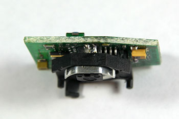
All Magna models from the TH to the TW (and the KH to KW Verada) used the remote shown below.
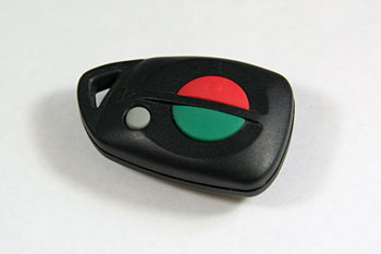
3rd generation Magna remote
I have had issues with both the remotes for my TJ Magna failing to work,
and have heard from other people who have had similar experiences with remotes failing.
A closer look at the remotes indicated they stopped working because soldered joints
holding the battery holder onto the printed circuit board (PCB) were cracked,
thus resulting in a bad electrical connection.
This occurs because the battery holder is only attached to the PCB by two small
soldered tags. When subjected to significant force (ie, when a remote is dropped),
the weight of the battery and battery holder places too much strain on the solder joints,
resulting in the joints cracking.
These remotes are relatively easy to fix, and a few minutes effort is certainly cheaper
than purchasing a replacement remote from a Mitsubishi dealer.
Fixing the Remote
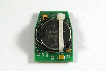
Disassemble the Remote
Separate the two halves of the remote using large screwdriver, or a small coin, to lever
them apart, and remove the printed circuit board (PCB).
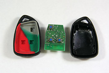
disassembled remote
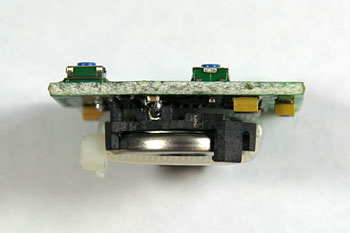
Check the Battery Holder
The most common issue is broken solder joints between the battery holder and the PCB.
The battery holder has two connections onto the PCB, and examine these two connections carefully
for cracks.
You may also be able to move the battery holder independently of the PCB.
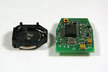
battery holder has broken off the PCB
The photo above shows a remote from a friend where the battery holder has become totally dislodged
from the PCB.
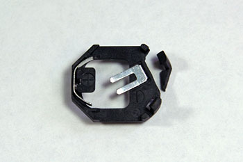
Resoldering the Battery Holder
To allow the battery holder to be resoldered onto the PCB, you'll need to cut a small corner off
the battery holder. If this is not done, it's virtually impossible to get a soldering iron
onto the joint on one side of the battery holder.
The photo below shows the section I typically remove from the battery holder. This can easily be removed
with a small hacksaw.
Note that one of the lugs that secures the battery in the holder is removed. However,
a cable tie will be used to secure the battery, as described below.
cut the battery holder
Resolder both the connections between the battery holder and the PCB, ensuring sufficient solder is used
to provide a good physical connection.
resoldered joints
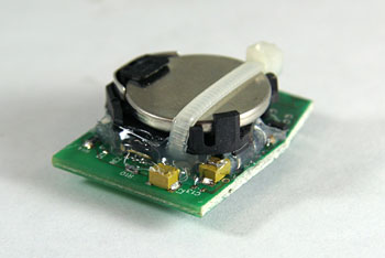
Securing the Battery
One of the lugs on the battery holder that secures the battery was previously removed, to provide
access to resolder the joint.
Use a small cable tie to secure the battery in the battery holder.
cable tie to secure the battery
There should be sufficient room between the battery holder and the PCB to allow a small
cable tie to be used, as shown in these photos.
cable tie to secure the battery
To try to prevent the solder joints from breaking again in the future, I use
some hot-melt glue to secure the battery holder to the PCB, as shown below.
hot-melt glue to hold the battery holder
This hot-melt glue should prevent too much force being placed on the solder joints
that secure the battery holder onto the PCB in the event of the remote being dropped.
Reprogramming Remotes
Note that your local Mitsubishi dealer can reprogram remotes, but they
will charge you. Rather than paying your Mitsubishi dealer, you can
easily reprogram the remotes yourself in a few minutes.
You'll need to have all the remotes for the car when programming, because
once you place the car into program mode, it will forget all previous remotes.
- To place the car into program mode, turn the
ignition between ACC and IGN three times within a 5 seconds period, and
then leave at the IGN position.
- The hazard lamps will flash once to indicate the car is now in program mode.
- Within 5 seconds of this acknowledgment, press any button on the first remote.
- The hazard lamps will flash once to indicate acceptance.
- Within 5 seconds press any button on the next remote to be
taught. This process may be repeated for up to four keys.
- Program mode will be terminated by any of the following events:
- The ignition is turned off.
- More than 5 seconds have elapsed since the last
valid key code.
- Four keys have been taught to the BEM.
- No correct data has been received in 10 seconds.
last updated 24 Mar 2026
|
|


