|
|
|
|
|
|
|
Antenna Comparison Testing
(first published February 2003)
This page details the testing method and results when testing
some downpipe waveguides, a collinear, some biquads, a cantenna,
and a modified Conifer dish.
Background
Over the past several months, I'd constructed a number of antennas,
including some biquads, an 8-element collinear omni,
and a cantenna, and
Marcus had recently constructed some 8-slot 180-degree waveguide antennas
using cheap downpipe.
We wanted to test the waveguides, and compare the performance of the
various antennas.
By testing all the antennas in a single session, using identical configurations
in the same location, allows us to easily compare the performance of the
various antennas, as there are minimal factors which would be affecting
the results.
Test Equipment
We used two laptops, one at either end of our wireless link.
The specs for the laptop at the remote end:
- Pentium III 1GHz with 128Mb RAM
- Enterasys RoamAbout wireless card
- Windows 2000 SP2
- Enterasys 7.44 drivers and client utility
- running on battery power for the duration of the tests
The specs for the laptop at the antenna end:
- Pentium III 700MHz with 256Mb RAM
- Enterasys RoamAbout wireless card
- Windows 2000 SP2
- Enterasys 7.44 drivers and client utility
- running on battery power for the duration of the tests
Antennas
We had the following antennas to test:
- modified 24dBi Conifer (ex-Galaxy) dish
- cantenna
- two biquads
- two 8-slot 180-degree downpipe waveguides
- 8-element collinear omni antenna
The 24dBi Conifer dish has been modified by myself,
with a custom-made copper and brass dipole. This is my reference antenna,
and has been used in previous antenna testing sessions
(referred to as Feedhorn #3 in the May 2002
Conifer Antenna Testing, and m3
in the September 2002 Conifer Antenna Testing II).
The cantenna was constructed by myself using a steel can with diameter of 100mm,
and a length of 175mm, with a panel-mount N connector riveted into the appropriate
location.
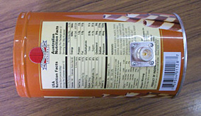
the panel-mount N connector
| |
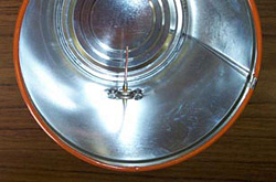
the feed inside the cantenna
|
The first biquad (referred to as biquad1) was constructed in a similar way to
those made by Trevor Marshall, and has two "lips" on the sides
of the reflector. This biquad had approximately 2m of CNT-400 coax attached to it.
The other biquad (referred to as biquad2), is the one featured on my
Biquad Antenna Construction page. A short length of
CNT-400 coax is attached to this biquad.

biquad1
| |

biquad2
|
Note that biquad1 has not been built optimally, as it is not correctly impedance
matched (due to the use of the wire stakes to mount the biquad to the reflector).
Biquad2 has been constructed with the coax extending through
the reflector, encased in the copper pipe for additional strength.
The collinear was constructed using 8 elements of CNT-400 coax, as per
the details at wireless.gumph.org,
with the dimensions appropriately adjusted to suit the velocity factor of
CNT-400 coax.

the collinear nearly complete
It has been mounted inside a length of 25mm electrical conduit,
to provide some physical strength, and to weather-proof it.
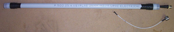
the completed collinear
Marcus constructed the two 8-slot 180-degree
waveguides
using readily available downpipe.
The first is based on Trevor Marshall's
design (referred to as the TM waveguide), while the second is based
on Rob Clark's
design (referred to as the RC waveguide).

the two completed waveguides
(RC waveguide on the left, TM waveguide on the right)
Test Setup
We placed one laptop on the parcel shelf of a car which we parked approximately
200m down the road. No external antenna was connected to this laptop -
we were relying on the internal antenna in the RoamAbout card.
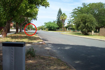
the remote laptop is in the red car (circled), approx 200m distant,
with the top of a waveguide shown in the foreground
Each antenna was connected to the wireless card in the other laptop using a
2 metre length of RG213 coax (terminated with a male N connector at one end,
and a female N connector at the other end), and an appropriate pigtail,
with the wireless cards at both ends configured to operate in ad-hoc mode.
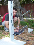
testing the waveguide
| |
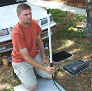
testing the collinear
| |
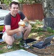
testing the cantenna
|
Testing Methodology
The "Link Test" mode in the Enterasys Client Utility was used to monitor the link strength,
with each test configuration being monitored for a couple of minutes.

the Enterasys Client Utility displaying link statistics
Once the reported link details had stabilised, the SNR, signal strength and noise
level were recorded for both the local and remote ends of the link
were recorded.
All antennas were tested in both horizontal and vertically polarised
orientations.
For horizontal polarisation, the waveguides are vertical, the biquad
is vertical, the collinear is horizontal, the cantenna feed element
is horizontal, and the Conifer dish is vertical.
For vertical polarisation, all antennas were rotated 90 degrees.
The waveguides were briefly tested on channels 1, 6 and 11, and
as they performed best on channel 6, this channel was used for all
subsequent testing of the waveguides and all other antennas.
As we wanted to plot azimuth graphs for the two waveguides, we measured
the signal, noise and SNR details after rotating the waveguides at
10 degree intervals.

testing the waveguides at different angles
Signal readings at different rotation angles of the waveguides were only
made with the waveguide horizontally polarised, as it is designed to
operate in this orientation.
Test Results & Calculations
The tables below show the recorded signal, noise and SNR values
for both the local (ie, the laptop connected to the antenna) and
remote (ie, the laptop in the car) ends of the connection.
horizontal polarisation:
|
|
local
|
remote
| |
antenna
|
SNR
(dB)
|
signal
(dBm)
|
noise
(dBm)
|
SNR
(dB)
|
signal
(dBm)
|
noise
(dBm)
| |
TM waveguide
|
18
|
-80
|
-99
|
22
|
-75
|
-97
| |
RC waveguide
|
25
|
-76
|
-100
|
24
|
-73
|
-98
| |
Conifer
|
30
|
-70
|
-100
|
30
|
-70
|
-100
| |
biquad1
|
19
|
-81
|
-101
|
21
|
-80
|
-100
| |
biquad2
|
19
|
-80
|
-100
|
21
|
-80
|
-101
| |
collinear
|
15
|
-83
|
-99
|
18
|
-82
|
-100
| |
cantenna
|
17
|
-84
|
-100
|
22
|
-79
|
-100
|
vertical polarisation:
|
|
local
|
remote
| |
antenna
|
SNR
(dB)
|
signal
(dBm)
|
noise
(dBm)
|
SNR
(dB)
|
signal
(dBm)
|
noise
(dBm)
| |
TM waveguide
|
30
|
-70
|
-100
|
28
|
-74
|
-100
| |
RC waveguide
|
30
|
-70
|
-100
|
29
|
-72
|
-100
| |
Conifer
|
37
|
-64
|
-100
|
34
|
-66
|
-100
| |
biquad1
|
26
|
-74
|
-100
|
23
|
-78
|
-100
| |
biquad2
|
24
|
-78
|
-100
|
20
|
-80
|
-100
| |
collinear
|
23
|
-78
|
-99
|
20
|
-80
|
-100
| |
cantenna
|
26
|
-74
|
-100
|
25
|
-76
|
-101
|
To calculate the gain of each antenna, the remote signal readings were
normalised, using the recorded results for the 24dBi Conifer dish.
The remote signal readings provide an indication of the transmit performance
of each antenna.
Note that the gain of the Conifer dish has been conservatively estimated
at 22dBi.
The normalised results for each antenna are:
horizontal polarisation:
|
antenna
|
gain
(dBi)
| |
Conifer
|
22
| |
TM waveguide
|
17
| |
RC waveguide
|
19
| |
biquad1
|
12
| |
biquad2
|
12
| |
collinear
|
10
| |
cantenna
|
13
|
| |
vertical polarisation:
|
antenna
|
gain
(dBi)
| |
Conifer
|
22
| |
TM waveguide
|
14
| |
RC waveguide
|
16
| |
biquad1
|
10
| |
biquad2
|
8
| |
collinear
|
8
| |
cantenna
|
12
|
|
Azimuth plots of the transmit performance have been generated for
each of the waveguides, showing the performance over 360 degrees.
Note that testing was only performed over 180 degrees, but
some quick tests indicated the results for the other 180 degrees
were within 1 or 2 dB.
azimuth plot of the TM waveguide
(normalised dB)
| |
azimuth plot of the RC waveguide
(normalised dB)
|
Refer to Marcus'
page
for more details on the waveguide test results, and additional azimuth plots.
These azimuth plots almost exactly match the theoretical azimuth plots
which Trevor Marshall shows on his
webpage.
Comments & Conclusions
By testing all the antennas in the same location, on the same day,
using the same hardware at both ends, we've attempted to minimise
any factors which may affect the results.
When calculating the normalised gain of the antennas, we assumed the
gain of the 24dBi Conifer was 22dBi.
Our results generally agree with the antenna gains other people have reported.
Claimed gains for the biquads are typically 10-12dBi, while we measured 8-12dBi.
Interestingly enough, biquad1 measured 10-12dBi, while biquad2 measured 2dBi
less when vertically polarised, despite having a stub (the mount between the
reflector and the quad itself) which is impedance matched.
I'd suggest these differences are due to the lips on biquad1, which would
reduce the beamwidth of the antenna somewhat.
Various people have reported gains for the 8-element collinear anywhere between
6-10dBi (6dBi for RG-213 construction, while my collinear uses CNT-400),
while we measured 8-10dBi.
Similarly, people have reported cantenna with gains varying from 10-14dBi,
while my cantenna measured between 12 and 13dBi in these tests.
The theoretical gain of the TM waveguide is 15dBi (according to
Trevor Marshall),
while commercially available 8-slot 180-degree waveguides are
marketed with gains between 14 and 16dBi.
Our results show the gain of the TM waveguide being 14-17dBi,
and the gain of the RC waveguide being 16-19dBi.
The RC waveguide provides approximately 2dBi more gain than the TM waveguide,
which is consistent with
Rob Clark's
testing.
Note that the dimensions of the downpipe are slightly different than the
aluminium tubing used by Trevor Marshall, but the slot spacing was not
adjusted to compensate for this.
However, when constructing the RC waveguide, the measurements were
re-calculated to suit the downpipe dimensions, and was adjusted to have
a air column length of 5 wavelengths (while the TM waveguide has an air
column length of 4.75 wavelengths).
We intend to perform some more testing with the waveguides,
and I'll update this page with the results, when they are available.
During our testing, we noticed that while the cantenna and the
Conifer dish have a very narrow beamwidth (Conifer specs say 7 degrees),
the biquad have a very wide beamwidth.
With such a wide beamwidth, the biquad is extremely easy to aim,
while antennas with a narrow bandwidth can be more difficult to aim.
References
Conifer (ex-Galaxy) Antenna Modifications:
Wave Guides:
Collinear Omni Antennas:
Biquads:
Cantenna:
Credits
Photos by ,
azimuth plots by Marcus,
other graphics by .
last updated 22 Oct 2013
|
|
|
|
|
|
|
|
|


