posted Monday, 24 August 2009, 21:45 (+0800), by Martin
Note: if you are looking for a review of the
functionality and features
of the Phottix Cleon II,
then please refer to
my review.
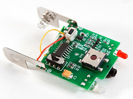
Phottix Cleon II receiver PCB
Phottix Cleon II
Earlier this year, I reviewed the Phottix Cleon II. It's a wireless shutter release that operates on 433MHz, with a range of upto 100m, and uses a smart-code system with 16,000,000 combinations instead of DIP switches to set the channel.
Instead of the camera cable being hard-wired into the receiver, Phottix use a 3.5mm stereo socket on the receiver, and Phottix make cables to suit various cameras. This allows a Phottix Cleon II to be used with different types of cameras, providing you have cables available to suit the different cameras.
Refer to my review of the Cleon II for more details on functionality and features.
I was interested in taking a closer look at the circuitry inside the Cleon II, and after noticing something rattling inside the receiver, I decided to open up the Cleon II.
Here are the Cleon II transmitter and receiver before disassembly:

Cleon II transmitter
|

Cleon II receiver
|
Transmitter
The transmitter has two small screws holding the two halves of the case together, and once this screw is removed, the two halves separate very easily.
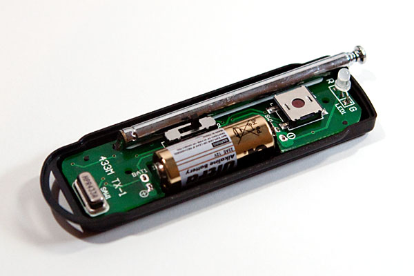
transmitter with cover removed
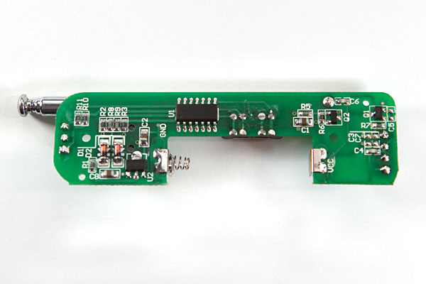
underside of transmitter PCB
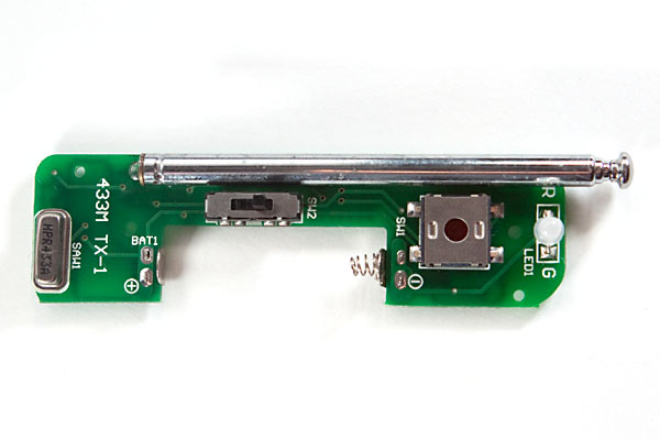
top of transmitter PCB
Receiver
A single screw holds the receiver together. However, the two halves of the receiver case are also clipped together tightly, and will require some gentle persuasion to separate the halves.
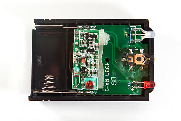
receiver with cover removed
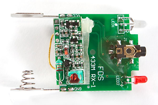
underside of receiver PCB
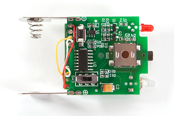
top of receiver PCB
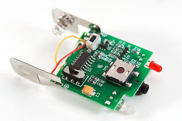
top of receiver PCB
The Rattle
The cause of the rattle in the receiver was quickly determined. The hot-melt glue holding the small daughter board to the underside of the main PCB had detached itself from the main PCB, and some small pieces of dried-up hot-melt glue had broken off, and were loose. The daughter board itself was only being held in place by the wires attaching it to the main PCB.


